Thursday, November 30, 2006

Control Panel Mock-Up

Well, it's time for the daily control panel update - it seems like this has become a sticking point for my cabinet. Last night I finished making a mock-up of the control panel using the design with the 4 buttons on the right.


The top of the control panel will be right where the bottom of the T-square is located. The bottom of the CP more or less goes right to the bottom of the panel (I just need to rip it straight but if you look closely you can see the pencil line). Also note that all of the admin buttons will be black on the final CP - I just didn't have enough extra lying around.

I'm thinking it is one button too tall and that I need to seriously consider relocating or removing the coin button so only 3 buttons are on the right. It's not that I don't have the room for it - this is strictly on proportions by eyeballing it.

Mini-buttons: I have thought about using mini-buttons in order to shrink the overall design but this cab is for Bella, not me. I know there's not much difference in what a mini button does versus a regular one (you just press it, duh!) but for some reason I think the size will make it easier for my daughter to understand and to press.

My goal is to keep everything on the same plane (no buttons on the front) and all of the buttons the same size. I know this isn't the ideal solution for a regular cab but I think it is what will make it easiest for her.

I'm leaning towards the shorter "upsidedown L" shaped design for the admin buttons that I posted yesterday or possibly removing the coin button altogether and just hoping she can understand that you have to insert a quarter if you want to play. I'll probably go with the "upsidedown L" shape for simplicity's sake and sacrifice a little bit of uniformity in the overall layout.

Time to go make Control Panel Mock-Up #2.

Thanks for looking!!

Wednesday, November 29, 2006

Control Panel Design #3

OK, I started to make a mock-up CP last night and the button layout forced the height of the CP to be 6-7/8" tall which seems a little high. I have room for it but that means there is a lot of dead space on the control panel (which I could use to install a spinner or something) so I'm not sure overall how it will look. I'm going to go ahead and finish drilling out the holes for the action buttons and joystick (which is arriving today!) and maybe even cover it in black vinyl (if I have enough) to see what the "finished CP" will look like. If I decide to scrap it, no big deal - it only takes an hour or so to layout the buttons and drill out the holes...

Another design to shrink the overall height:

Also, another idea someone suggested would be to put the "coin" button on the face of the control panel to save space on top. This is making me crazy!

Thanks for looking!!

Tuesday, November 28, 2006

Control Panel Design #2

OK, after only one day of sleeping on it and asking for some opinions over at BYOAC I've decided to redesign the control panel just a little bit to make it more Bella friendly. My first thought was that having the Exit button all the way to the right might not be the best idea because my right hand will be constantly moving over the action buttons and could still accidentally hit it at an inopportune time. My next redesign was to just flop the admin buttons on the top row like this:

I like the new placement of the Exit button but I really don't like where the other 4 admin buttons ended up. The right side of the control panel looks too cluttered in this configuration. However, several people over at BYOAC answered my request for some criticism and suggested that I keep the Exit button on the left and the admin buttons on the right but line them up vertically. Genius!

I also moved the action buttons and joystick to the left a little so my right hand wouldn't be resting where the admin buttons are. I might have to make the control panel a bit taller but I think I have the room - as it stands now 6.5" might be tight for four buttons because I need to leave at least .75" on the bottom to accommodate the panel for the front of the control panel.

I really like the current state of the control panel and I'm going to make a mock-up out of MDF to test it out (so of course this is still subject to change!).

Thanks for looking!!

Day 6: Marquee Top

There's nothing magical about the installation of this panel. I just cut an 18.5" piece of MDF to cover the speakers and marquee light in the top portion of the cabinet. I haven't glued it into place yet because once I do the speakers are going to be extremely difficult (if not impossible) to get to if they aren't working properly. I think there is enough room to get a mini screwdriver in there but I won't be able to see a thing. Also, I want to add some type of lining to ensure that no light will escape from this area in case the panels aren't perfectly aligned.

Anyway, I made sure to cut the marquee top panel so it is flush with the back panel and is lined up with the bottom marquee panel as close as possible. The marquee retainer will eventually cover the ends of the MDF and frame the marquee.

That's really all there is to it. Here are some shots of what the upper part of the cabinet will look like once everything is glued in place.


Tips:
1. Make sure that you do not install the interior wood strips so the ends are flush with the ends of the marquee panels. If you do that it will create 4 square shadows in the corners behind your marquee. This is actually a tip that should have been given a while ago but better late than never.
2. Try to make everything as flush as possible. Light will escape out of any gaps where two pieces of MDF come together. I am going to line the inside with aluminum foil or something shiny for maximum reflection and to also seal any gaps that might let light out.

Thanks for looking!

Monday, November 27, 2006

Control Panel Design

It's now time to put some serious thought into the design and layout of the control panel. This is probably one of the most important things anyone will have to do in design an arcade cabinet. There is no such thing as an all-in-one solution but I still want to be able to play the most amount of games as possible. Since this is going to be a vertical cab and really limited to the classics I think 3 buttons will do the job nicely - there aren't many that require more and the only one I can think of that I might ever want to play is Super Punch-Out!! but I don't think one game is worth an extra button on the control panel. I've said it before but I also want this thing to be simple to use.

Along with the action buttons that will control jumping and shooting or whatever while I am playing I'm going to need "admin" buttons in order to make a game selection from the list, to insert a coin and to pause when I'm playing. I think 5 of these buttons will suffice (player 1 start, player 2 start, coin, pause and exit back to the game list). Here's my first stab at it:


As you can see, I'm trying to keep the admin buttons all in a row on the top and then center the joystick and action buttons so it is comfortable while playing. I thought about this design for a few days and even made a mock-up (with different colored buttons) to see how it would look.


I didn't really like the spread out look of the admin buttons so I decided to redesign it a little bit. Here's what I came up with:


I clustered all of the admin buttons to the left except for the exit button - I don't want to accidentally hit this in the middle of a game when I'm reaching for the pause button to go grab a cold beer or something! I also rearranged the action buttons a little bit because I think it will be more comfirtable to play this way. Unless I think of anything radical in the next week or so I'm going to call this the final design.

Thanks for looking!!

Sunday, November 26, 2006

Day 5: Speaker Installation


Installing the speakers was a little tougher than I anticipated (just like everything else). I thought it was going to be a 20 minute job but it ended up taking well over an hour. I bought a set of cheap 2.1 speakers from CompUSA to put in the cabinet. Most older arcade games have very primitive sound so this is more than adequate to recreate the authentic arcade experience.

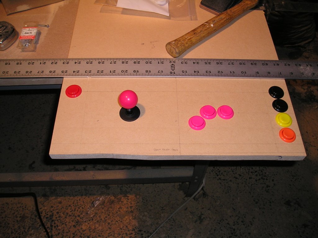
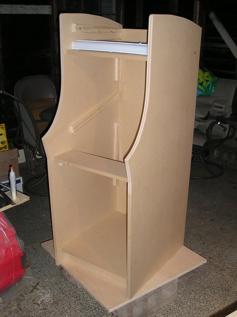
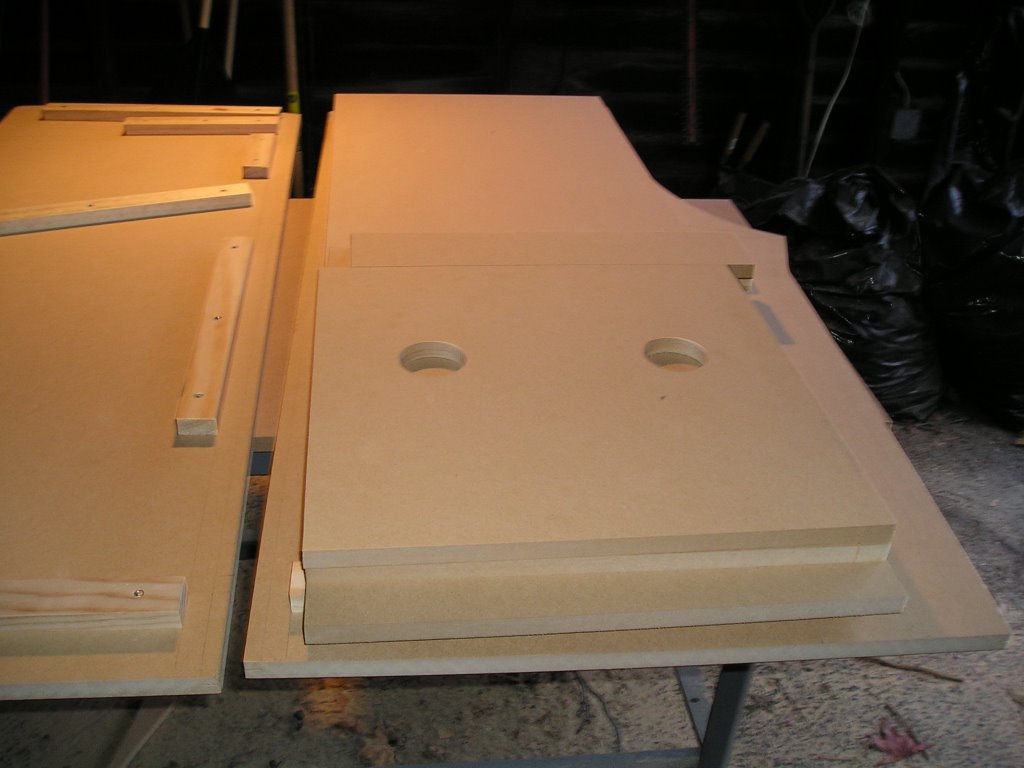
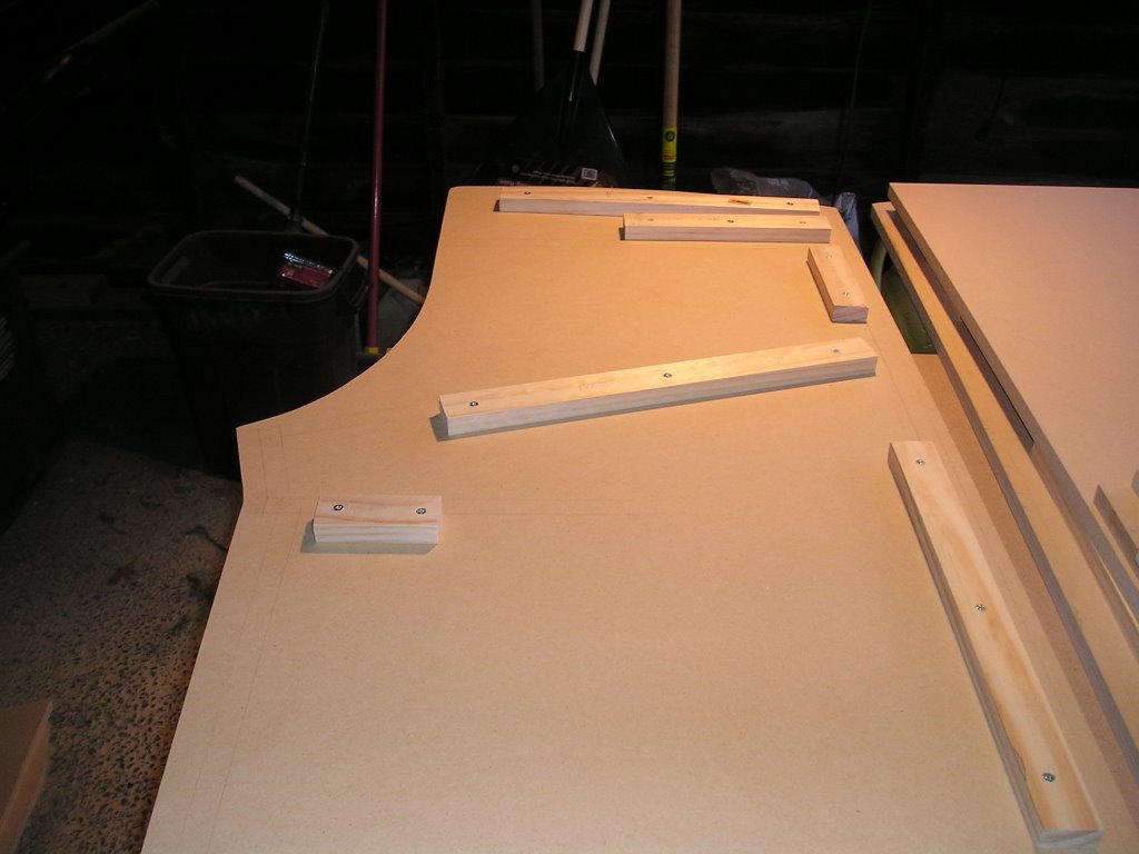
I already had the holes cut out in the panel where the speakers were going to be mounted. The holes are 2.5" in diameter and the speakers are 2.0" in diameter. I ended up removing the speakers from the casing for installation but I still used the front panel of the speaker casing to secure the speakers in place.


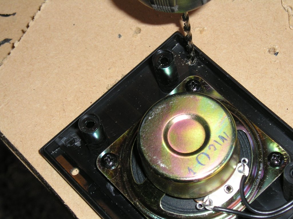
As you can see from the picture, I totally destroyed the brand new speakers I bought. First, remove the front cover. This pops off quite easily to reveal 4 screws holding the casing together. Next, using a thin screwdriver remove all 4 screws which will separate the flat front piece from the large plastic piece that encases the speaker. Save the screws! I used them to secure the speakers to the cabinet. Be careful here though. The wire that is attached to the actual speaker is also attached to the back casing and you don't want to break anything. The trick here is to make a big hole in the back casing so the wire and fit through and be removed. I used a saw to cut a groove in the back and then jammed a screwdriver inside and twisted it around until I had a hole big enough to get the wire through.


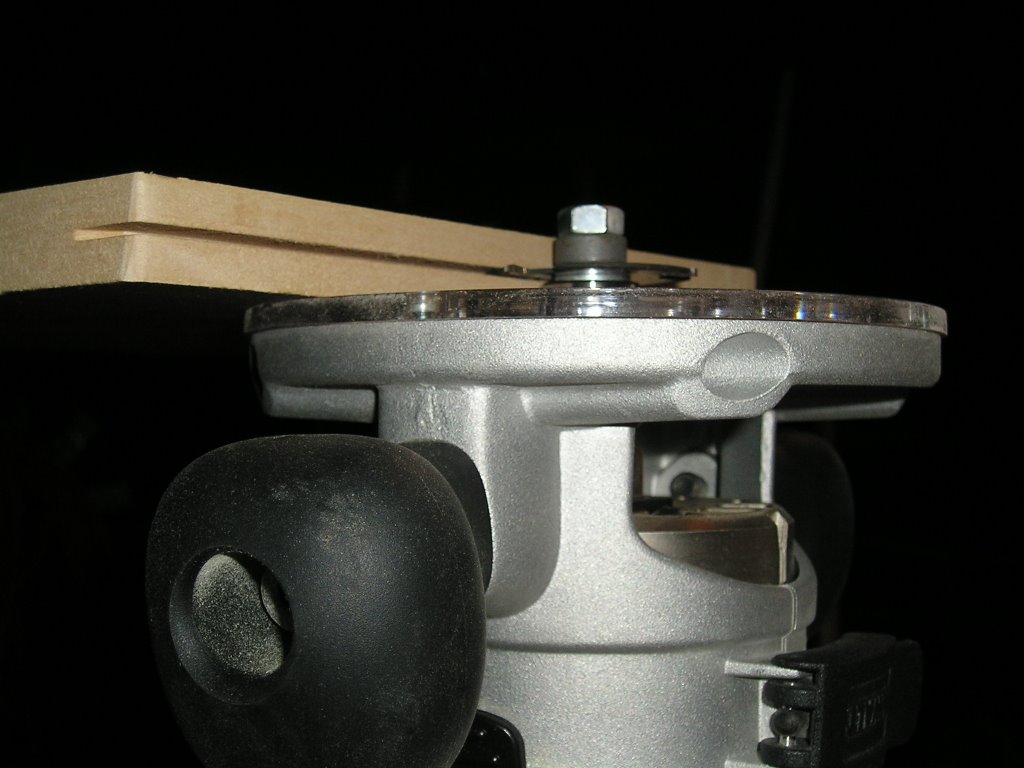
Once the speaker is out of the casing you should be left with the speaker attached to the front panel and the long wire coming off of it as shown in the picture above. The next thing I did was drill 4 holes in the front panel in order to secure it to the speaker cutouts in the cabinet. In the above picture you can see the drill on the top and one of the holes I drilled on the left- I drilled a hole in each corner the exact size of the screws I saved when I took the speakers apart.


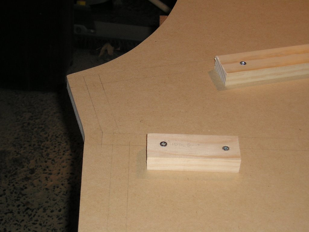
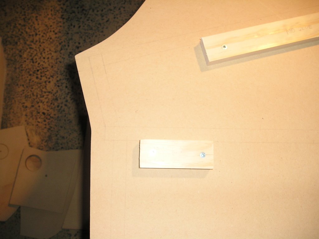
After you have all 4 holes drilled out, put the speaker in place and make sure it is lined up from underneath. Then use a pencil to mark where the screws are going to go and drill pilot holes. Finally, screw the speakers in place!


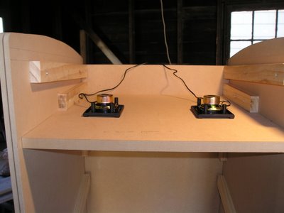
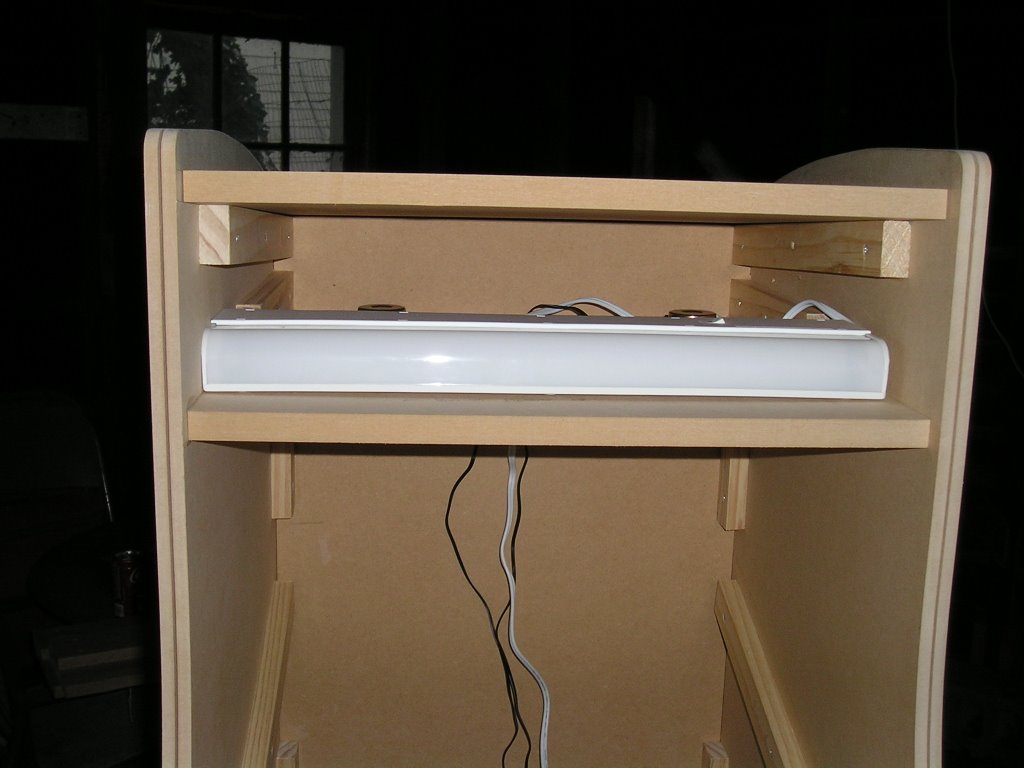
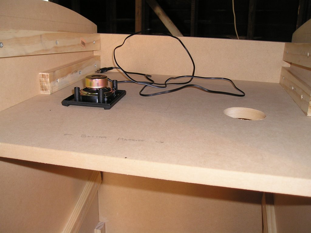
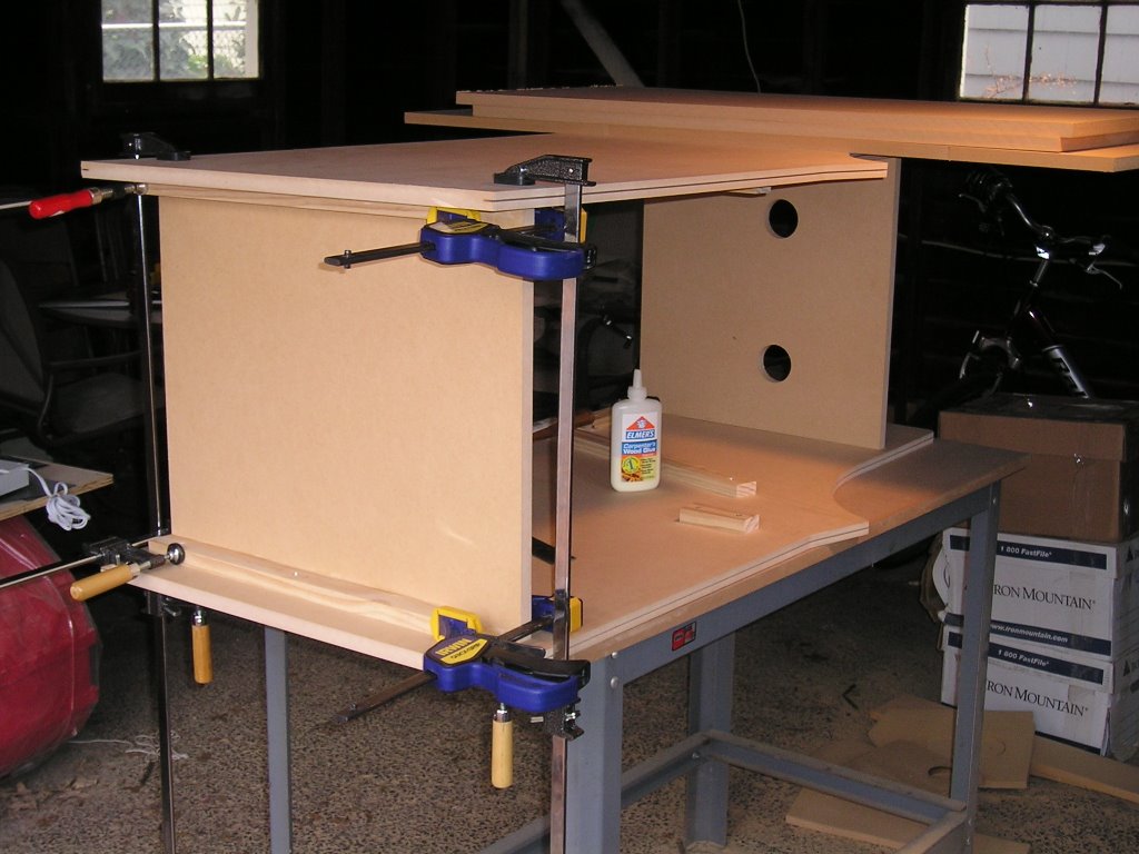
That's all there is to the speaker installation however you need to do something with the speaker wires - they need to connect to the bass tube which will be located at the bottom of the cabinet. and they can't hang out over the back! This "problem" has a simple solution - I drilled a 1-1/8" hole up against the back panel of the cabinet so the speaker wires could fit through and drop down to the bottom. I also made sure the hole was wide enough to accomodate the power cord for the marquee light that will be installed in front of the speakers because the power strip is also going to be installed in the bottom of the cabinet.

That's all for now!

Tips:
1. Go slow and be very patient when taking the speakers apart. I actually ruined one because I was rushing to finish (good thing I had a spare from an old project).
2. When drilling the holes in the plastic casing make sure everything is secured to the work bench or you are holding on very tightly. Drill slowly.
3. Test everything on scrap MDF. Before I did anything to the cabinet I secured one speaker to a some scrap MDF just to see if it would work properly.

Thanks for looking!

Friday, November 24, 2006

Control Panel Issues

I've run into a little snag - I am still trying to work out how the control panel and monitor bezel are going to interact with each other as well as how the bottom of the control panel is going to transition to the bottom portion of the cabinet (the top of the coin door panel). I ended up staring at the cabinet for a solid 45 minutes without doing a single thing because I want to make sure I do this right.

This is a picture of the problem area:


Hopefully the pencil lines are viewable - they show where the control panel will go. Right now the control panel top/bezel is going to be at a 90 degree angle to the control banel bottom. I should note that the small support piece in the middle of the cabinet (as shown in the picture) is not glued in place so it is moveable.

I think I want the control panel and bezel to be made out of one sheet of MDF except I run into problems when I start thinking about adding the smoked glass overlay (3/16" thick) and potentially a thin posterboard bezel to frame the monitor closely. I am probably going to offset the control panel top and monitor bezel by 1/4" to accomodate the glass and the posterboard but this might be tricky.

The monitor is going to be a 17" Dell LCD computer monitor. I plan to cut a hole in the MDF bezel panel the exact size of the outer circumference of the monitor case so I can have the LCD screen flush with the MDF bezel panel. The monitor will be supported from behind and I plan to add a thin piece of black posterboard on top to cover the edges of the monitor and make it look nice. I'm also planning to cover the entire control panel with Happs black vinyl so it will be able to withstand a little abuse from my daughter.

The next issue to resolve is how the angled front of the control panel meets the middle support piece. The only reason this middle piece is there at all is to frame the hinged coin door panel on the top. I wanted a small lip on the top of the coin door panel so it didn't just butt up against the front of the control panel. This lip will also hide the fact that the coin door panel opens.

I think the follwing diagram is a nice solution but it also means I will have to cut the MDF at some very odd angles to make everything fit.


Oh well, I hope this works. I also have to keep in mind that I need access to the underside of the control panel in order to install the controls and wire everything. My head is going to explode!!

Thanks for looking!!

Cost Breakdown to Date #2

Last week I ordered the Smart Strip power supply for $37.31 ($26.99 + $3 for a black cord + taxes and shipping). Today I placed the order for the Ultimarc 360 joystick and a few accessories for $100 to go along with it - it's is expensive but hopefully worth it. I also just went to Home Depot and bought the two hinges ($6.99) and the magnetic clasp ($0.89) for the coin door panel for $8.43 (after taxes). Finally, I hit up CompUSA for some cheapo 2.1 speakers for $21.39 (after taxes). Here's the breakdown so far:

Bought:
MDF: $35.00/4'x8' sheet x 2 sheets = $70
Screws: $5.98/box x 1 box = $5.98
18" flourescent light (for behind marquee): $8.97
Wood support strips: $0.97/foot x 12 feet = $11.64
3 buttons, balltop joystick, t-molding from Dream Arcades = $32.75
Smart Strip power supply = $37.31
Hinges and magnetic clasp = $8.43
Ultimarc 360 Joystick = $59.00 (+$14.00 shipping)
Encoder Harness (for button wiring) = $8.00
Restrictor Plate (to shorten joystick throw) = $14.00
Hard Spring (to tighten joystick movement) = $5.00
Computer Speakers (2.1) = $21.39

TOTAL so far: $296.47

To buy:
Coin Door
Two (2) black pushbuttons
Marquee Retainer
Marquee
Dell 17" LCD Monitor
Primer/Paint/rubbing compound (for finish)
1/4" Glass (to cover monitor)
Black Posterboard (for bezel)

Monday, November 20, 2006

Day 4: Is That An Arcade Machine?

It's official. What was once just two sheets of MDF now unmistakeably resembles an actual arcade cabinet. I didn't really do anything yesterday except take the clamps off and stand it upright but it is still cool to see it take shape.

I also installed the kickplate and cut the cross piece for the middle which will give added support as well as provide a guide to frame the coin door panel. The coin door panel is going to be hinged and swing open so I can access the computer.

Anyway, here are some new pictures!


Thanks for looking!!

Saturday, November 18, 2006

Day 3: The Glue Up

I didn't do a lot of work today but I did get a chance to glue up the panels! I now have an actual 3D cabinet - it's starting to take shape - check it out!


Tips:
1. Dry fit everything first. You want to make sure everything fits together properly before applying the glue.
2. Use a light bead of glue on the edges. Make sure all surfaces are covered but you want to avoid a lot of squeeze out, if possible.
3. Clamp, clamp, clamp. You can never have too many for a job like this. Try and make sure you have at least one clamp on each edge of each surface you are trying to glue together.
4. Make sure everything is square!

Tomorrow I'll be filling out the rest of the cabinet frame with the remaining cross pieces and hopefully putting the front door in place with the coin door cutout. Then it should be ready to be painted!

Thanks for looking!!

Wednesday, November 15, 2006

FINAL Marquee Design!!

A HUGE thanks to everyone who submitted a marquee design for me. I decided to go with the one made by megashock5 but modified to incorporate the color scheme of the second one submitted by onetrackmind. Here it is:


I wasn't sure about having green as the only secondary color in the design because it would be the only place on the entire cabinet where green would appear. I think the "rainbow" of colors doesn't made any one color stand out over another. I am going to wait a week or two before ordering the marquee from mamemarquees just in case I think of any other minor tweak because once it is printed I've got to live with it. Besides, I'm at least two weeks away from being able to install the marquee if all goes according to plan.

Thanks again megashock5 - Bella is going to love it!!

Day 2: Speaker Holes

The last thing I did today was cut a pair of 2-1/2" holes in the bottom marquee shelf for the speakers - I will have to also cut a smaller 1-1/4" hole to feed the plug from the marquee light and speakers through but I think I need to wait until the thing is assembled so I can get an exact placement. The computer is going to be in the bottom of the cabinet and the light and speakers have to connect to the computer somehow! To accomplish this task I used a 2-1/2" hole saw and my drill. It was pretty simple - here are the results:


Tips:
1. After you find the center point where the holes are going to be, use a nail and lightly tap it into the center point to make a mark so the drill bit will be lined up properly.
2. When cutting out the holes apply light pressure and let the saw do the work.
3. As you cut through, make sure the drill and saw are perpendicular to the work piece.
4. Move the saw in and out of the hole very slowly once you begin cutting - this helps the sawdust escape so the saw can cut deeper. Drill the hole in several steps if you have to.
5. Make sure you clamp the piece to the work bench with a sacrificial piece of wood or MDF underneath. You don't want to ruin your work bench! It took way longer to do all of this stuff than I thought it would but that's always the case and I should know better by now not to plan too much ahead. Next weekend my father is coming over and we are going to put everything together so it should start looking like a real arcade cabinet by then. I can't wait.

Thanks for looking!!

Tuesday, November 14, 2006

Day 2: Cabinet Back

The next thing I did was cut out the cabinet back. This was a little tough to do because it had to be 50" long by 18.5" wide and I don't have my table saw set up yet. Also, my t-square and longest straightedge is only 48" long (and, as I found out while trying to make the cabinet back, not actually square) . I had to think about this one for a while before coming up with a solution that I think worked quite well. I had a fresh piece of MDF and I measured 18.5" from the long factory edge (the 8' length) on both ends. Next, using my nonsquare t-square I connected those points the best I could with a pencil line and then I used my jigsaw to make a rough cut about 1/8" wide of the line. Then, I placed the other 8' factory edge of the MDF on top of my pencil line making sure that the two points I measured previously were touching the edge and clamped the two boards together. The sloppy pencil line doesn't matter as long as the two measured points are accurate (and the factory edges are straight!). Next, using my router with a pattern cutting bit and the straightedge I easily removed the excess material and had a perfectly straight edge. The back panel is now cut and ready for assembly.

These are the best pictures I have right now of the cabinet back but you get the idea. Note that nothing here is glued or nailed into place yet - I just clamped the pieces together to take some pictures.


Tips:
1. Since the factory edge of the MDF is straight, don't worry about your pencil line. As long as the edge is lined up exactly with your two marks on either end you will make a straight cut.
2. Clamp everything to the workbench before you use the router - you don't want the piece to slip!

Thanks for looking!!

Day 2: Support and Cross Pieces

This weekend was a bit of a disappointment. The Giants lost (damn Bears), I was finally kicked out of my NFL suicide pool with only 5 people left (damn Patroits) and my fantasy team (The Vampire Slayers) got killed too. To top it all off, I didn't make as much progress on Bella's Arcade as I had hoped. I spent about 8 hours total working on it but nothing major got done. It is nice to get a lot of the "grunt work" out of the way though.

The first task that I completed was finally installing the wooden support strips on both cabinet sides. This proved to be much more difficult than I had originally anticipated because you have to make sure that the wooden strips on one side are lined up exactly with their counterparts on the other cabinet side otherwise the shelves won't be level. To attach each strip I used a combination of wood glue and #8 wood screws (1-1/4"). I put a very light amount of glue on the wood strip only (there was almost zero squeeze out) and then carefully clamped it in place making sure the edge of the wood strip was exactly on the edge of the pencil line I laid out on the cabinet side. Then, depending on the length of the wood strip, I predrilled 2 or 3 holes with a 1/8" drill bit and then screwed the strips into the MDF.


Tips:
1. Make sure the bit is no more than 1-1/4" from the collet on your drill so you don't go all the way through the MDF when predrilling.
2. Double and triple check the alignment of the wood strips - it is vital that they are as even as possible on both cabinet sides.
3. Go slowly - this part is very tedious and very boring. If you rush you are more likely to make a stupid mistake.

Thanks for looking!!

Sunday, November 12, 2006

Marquee Designs!!!

I posted a request in the forums for help in designing a cool marquee for Bella's Arcade over at CheapAssGamer and Build Your Own Arcade Controls. I have no photoshop skills and I've received a few responses so far from some very talented (and generous) people. I will keep posting them here as they come in.

From peteloaf:

From megashock5:

From onetrackmind:


A huge THANK YOU to these guys for doing this for me. Right now I'm undecided as to which one to use. I'm leaning towards megashock5's design right now but I've got probably a month or more to think about it. I need to get this thing assembled and painted before ordering the marquee!

Thanks for looking!!

Cost Breakdown to Date

This thing isn't cheap but I definitely think it's reasonable. Plus, it's almost as fun to build the cabinet as it is to play the games! It's just the cost of having a hobby you enjoy!

Bought:
MDF: $35.00/4'x8' sheet x 2 sheets = $70
Screws: $5.98/box x 1 box = $5.98
18" flourescent light (for behind marquee): $8.97
Wood support strips: $0.97/foot x 12 feet = $11.64
3 buttons, balltop joystick, t-molding from Dream Arcades = $32.75

TOTAL so far: $129.34

To buy:
Ultimarc 360 Joystick
Encoder Harness (for button wiring)
Restrictor Plate (to shorten joystick throw)
Hard Spring (to tighten joystick movement)
Coin Door
Dell 17" LCD Monitor
Marquee
Marquee Retainer
Smart Strip (to plug everything into)
Paint/rubbing compound (for finish)
Glass (to cover monitor)
Black Posterboard (for bezel)
Computer Speakers

Day 1: T-Molding Slots

Once the sides were cut, and before any of the battons are screwed into place you should route the slots for the t-molding. This is a very easy thing to do but you have to have the right tools for the job. Using a slot cutting bit I was able to route the slots around both cabinet sides in about a 1/2 hour. It was easy!

The most important thing to do for this task is to make a few practice cuts on scrap MDF and fit a t-molding sample to make sure the depth of the cutter is set properly. You only get one chance to get it right on your actual sides and you don't want to have to start over now!


Here are some shots of the router with the slot cutting bit installed. There is a ball bearing that will ride along the edge of the cabinet side and a blade will do all of the cutting. The idea is to get the blade on dead center of the edge so the slot will be cetered and as a result the t-molding will be centered too. This is why it's a good idea to practice on scrap MDF.


The above picture should give you an idea on how this is supposed to work. Note that the router is upsidedown - you will be holding the router on top of the MDF as you route the slots.


This is what the edges of the cabinet sides should look like with t-molding slots routed.

Tips:
1. Double and triple check the router depth to make sure it is exactly centered.
2. Test your cut on a scrap piece of wood.
3. How to tell your slot is perfectly centered: Place your router upside down on the work table (off, of course). Put the test piece on the router base and slide it onto the blade. Next, turn the test piece upside down and do the same thing. If the piece slides onto the blade then you know it is centered. If not, make an adjustment and try again. It also helps to fit a piece of t-molding in the slot you just cut to see how it looks.

Thanks for looking!!

Day 1: Progress Pics!!

I finally got some actual, real work done on this thing and it's looking pretty good so far. The entire cab is made out of MDF. So far I've just cut out the sides and routed the slots for the t-molding. I also cut all of the interior battons out of wood for support so I can assemble everything soon.


The first thing I did was plot out the design onto the surface of one of the MDF sheets using a pencil and t-square. The curves were made using a string tied to the end of a pencil to act like a large compass. Once the shape was drawn as well as all of the interior panel lines so I know where everything is going, I cut out the cabinet side using my jigsaw. I did it freehand and tried to stay about 1/8" outside the line all the way around. When that was finished I used a straight edge and a pattern cutting bit in my router to make the straight edges perfectly straight. To cut the smooth curves I was very careful with the jigsaw and got as close to the line as I could taking my time as I went. Then I used a sanding block to sand to the line and make a smooth curve.


Once I finally had one side to the cabinet cut out, making the second one took about 20 minutes. I placed the good side on top of another piece of MDF and traced it with a pencil. Then I cut it out with the jigsaw to get a rough shape. Next, I clamped the original to the rough cut piece and used my router and pattern cutting bit to make a perfect match! Finally, I transferred all of the interior lines to the second piece (on the opposite side, of course since the two pieces should be mirror images of each other).


The next thing I did was cut out the interior support pieces - in the pictures they are placed in their appropriate spots where cross pieces will go but not fastened down yet. I am trying to be careful not to make any holes on the outside of the cabinet because I want it to look like a finished piece of furniture. All screws and supports will be on the inside and hidden from view.

That's all for now. Next up: routing the t-molding slots!

Thanks for looking!!

PINK Is The New Hotness!!!

Since this cabinet is for my lovely 2 year old daughter I've decided to go with a very pink theme. I want it to be as girly as possible and truely be her own personal arcade cabinet. I am going to be painting the entire thing a light pink on the outside and black on the interior. I'm also going to try and get a real shiny finish on the outside so the cabinet will be protected from juice spills and also easy to clean but I don't know how to go about doing that yet. I think you have to add many layers of paint while sanding in between each coat and then apply some kind of rubbing compound to get the shine. I will document that process when I get to it.

The buttons, t-molding and joystick ball top will be a darker pink from Dream Arcades to accent the cabinet. I've ordered the following parts so far:

3 pink buttons:


1 pink joystick. I only ordered this for the ball top. I'm actually going to be using the Ultimarc 360 joystick for this project but it does not come in pink. Most joystick balltops are just threaded on to the shaft so I'll just unscrew them and make the easy swap.


30ft. of pink t-molding. This is a plastic trim which will go around the edges of the sides to give the cabinet a finished look.


As for the marquee artwork, right now I'm just planning on a bright colorful marquee - the control panel will be covered in black vinyl so the buttons really "pop" and I don't what type of artwork I'm going to add to the sides yet, if anything.